Average-Value DC-DC Converter Control - MATLAB & Simulink
€ 31.50 · 5 (296) · In Magazzino
Di uno scrittore di uomini misteriosi

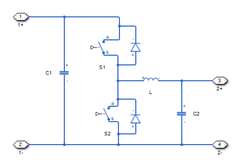
This example shows how to control the output voltage of a buck-boost converter.
Control the output voltage of a buck-boost converter. To adjust the duty cycle, the Control subsystem uses a PI-based control algorithm. An average-value DC-DC converter model is used to speed up the simulation. The input voltage and the system load are held constant throughout the simulation. The total simulation time (t) is 0.25 s. At t = 0.15 s, the voltage reference changes and the system switches from buck mode to boost mode.

Class E DC-DC Converter - MATLAB & Simulink
Modeling of DC/DC buck converter based on SMC using matlab /simulink

Average model of DC-DC Boost converter

Detailed Model of a 100-kW Grid-Connected PV Array - MATLAB & Simulink

How to Develop DC-DC Converter Control in Simulink - MATLAB & Simulink

MATLAB/Simulink-Based Grid Power Inverter for Renewable Energy Sources Integration
Controller-driven bidirectional DC-DC step-up and step-down voltage regulator - MATLAB

Power Electronics Simulation Onramp Overview - MATLAB & Simulink

How to make Average Model of Boost Converter in Matlab/Simulink
Developing DC-DC Converter Control in Simulink - MATLAB & Simulink

Controller-driven DC-DC step-down voltage regulator - MATLAB - MathWorks América Latina

Digital peak current mode control of isolated current‐fed push‐pull DC‐DC converter with slope compensation - Ghalebani - 2022 - International Journal of Circuit Theory and Applications - Wiley Online Library
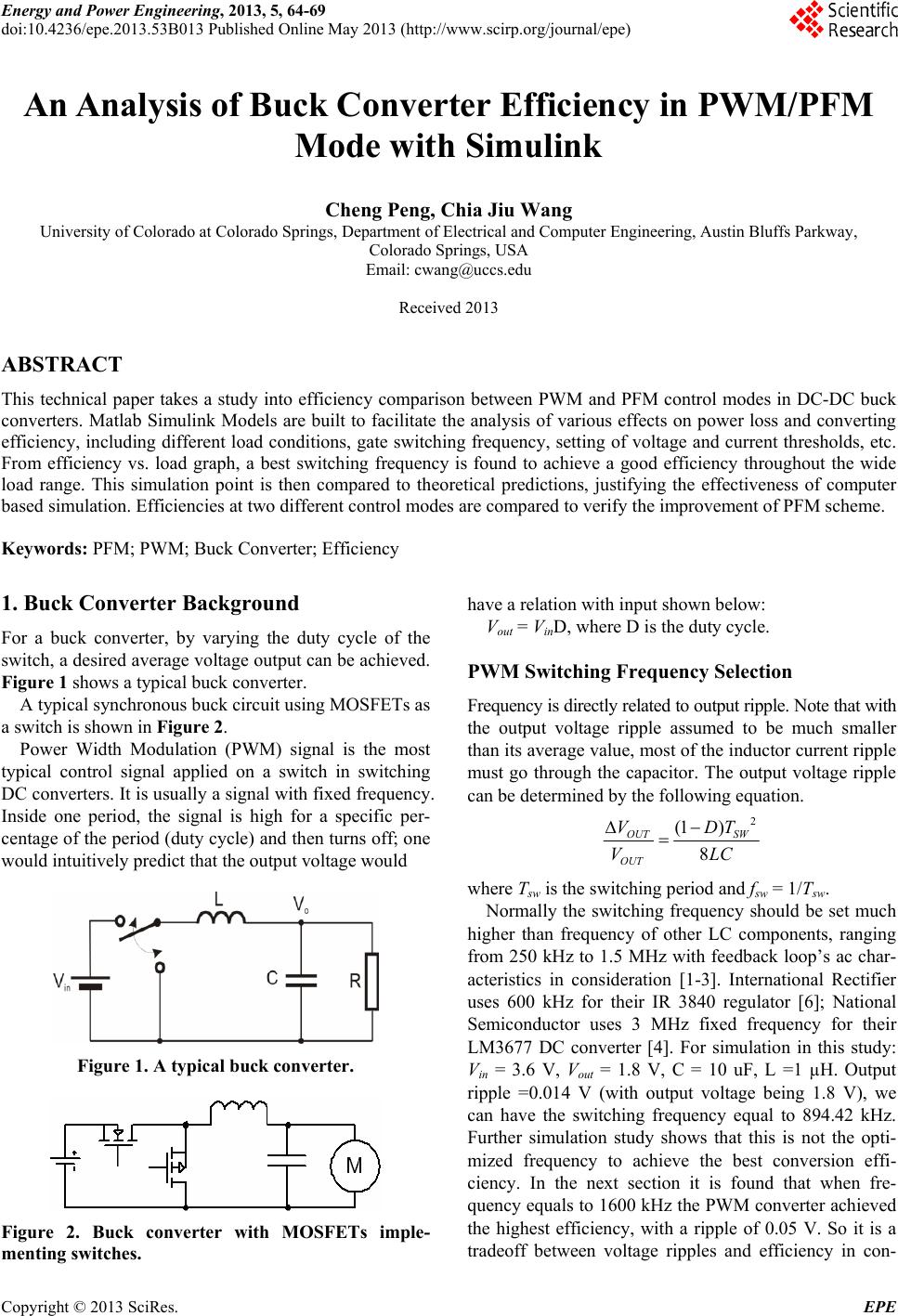
An Analysis of Buck Converter Efficiency in PWM/PFM Mode with Simulink

Linearize DC-DC Converter Model - MATLAB & Simulink - MathWorks Deutschland
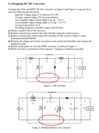
Solved 2.) Designing DC-DC Converter Consider the CUK and